Table des matières
Pmod OLED RGB
This page is about different controlers for the Pmod OLED RGB.
 ( figure source )
The main control sequence is partially based on the work of Clovis Durand and Xavier Marino, who adapted the original C++ sources from digilent in a VHDL architecture. This work was performed during the S8 transversal projects 2017 at ENSEIRB-Matmeca.
All these module have a common basis. they receive the system clock and reset. They also provide different signals that should be directly routed to the Pmod for its control : PMOD_CS, PMOD_MOSI, PMOD_SCK, PMOD_DC, PMOD_RES, PMOD_VCCEN and PMOD_EN. All these signals are outputs. The different modules of this page are designed to take full access to the Pmod, therefore, it is not possible to mix the different behaviors.
Module Generics
Some generic values are also always available on module.
- CLK_FREQ_HZ : This integer value should represent the main clock frequency expressed in Herz. It is mandatory to provide a correct clock frequency to the Pmod and to establish proper execution wait times. Default is 100MHz.
- PARAM_BUFF : To minimize hardware resources, input data of the module are expected to remain meaningful during the operation. If the design requires input values to change, setting this generic to True will add a register inbetween to allow this behavior without affecting the module functionnality. Default is False
- LEFT_SIDE : If connected on the right side of the development board is in its nominal position. But if connected to the left, it is rotated by 180°, which changes the screen layout and orientation. Setting this generic to True configures the Pmod so that the layout and screen orientation keep the same behavior than the right side conection. Default is False.
Generic Timing diagram
If PARAM_BUFF is False, input data are necessary while the ready bit is not set.
 ( figure source )
If PARAM_BUFF is True, input data are only necessary on the clock cycle at which the module reads the command bit.
 ( figure source )
Depending of the controler chosen, it is possible to display:
- bitmap : data represented by a local RAM (96×64, up to 16bits/pixel)
- nibblemap : Hex digits according to their individual position
- hexval : Hexadecimal values (up to 8 values, each value up to 64bits)
- decimval : Decimal 32bits values (not done yet)
- charmap : ASCii chars according to their individual position
- terminal : an ASCii stream like a terminal
- sigplot : Graphic waveforms Display
General Warnings
- The internal refresh rate of the OLED screen is relatively slow (10 to 15 Hz), therefore, the following modules were not optimized for speed but to minimize hardware resources
- This series of modules were developped recently and may still contain some bugs. If you find one, please report it by e-mail to Yannick Bornat with as much details as possible. It is also welcome to acknowledge that the module works fine if this the case.
- performing a module reset DOES NOT clear the screen.
- Any contribution for these modules is welcome, but please, keep in mind that the purpose of these module is to provide easy-to-handle interfaces for rapid development
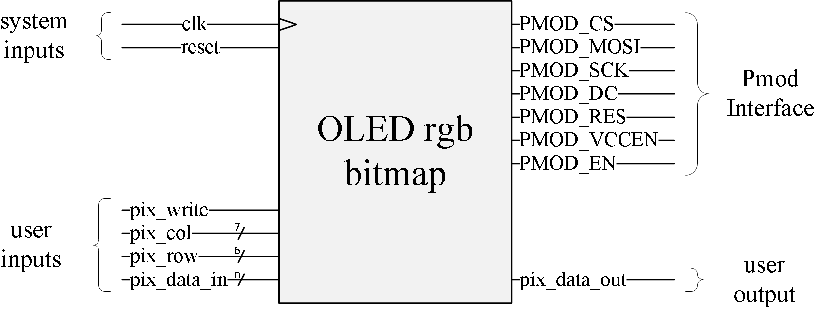
Bitmap
 ( figure source )
Usage
The pix_row and pix_col inputs are used to address any pixel of the 96×64 array. As a 7 bit std_logic_vector, pix_col may address columns up to 127. To avoid any problem, columns 96 to 127 are actually equivalent to columns 32 to 63. pixel 0,0 is the upper left pixel. If the screen is connected on a PMod on the left of the board, it is rotated by 180°, it is possible to compensate this rotation by affecting True to the LEFT_SIDE generic.
To affect a new color to a pixel, user should assert pix_write, address the concerned pixel and provide the new color on pix_data_in on the same rising edge of clk.
To read a pixel value, user should address the pixel and wait for the third following clock cycle to read the pixel value on pix_data_out as shown on the diagram below. Since read does not destroy data, there is no command, so as far as a pixel is addressed, it is possible to read its value. Read operations can be pipelined (see diagram below). Memory is read-before-write, so it is possible to read an write at the same time. The value output on pix_data_out will be the value of the pixel before it has been changed by the write operation.
 ( figure source )
Data is always accessible for read and/or write since the module uses another memory access to send data to the Pmod. Data is constantly being refreshed, so modifying the content of the bitmap memory will also modify the display. As the Pmod does not provide hardware to reteive feedback on the screen refreshing, it is not possible to provide refresh syncrhonization of double buffering features.
Hardware resources
still in progress… between 1 BRAM18k and 4 BRAM36k depending on synthesis parameters and bits/pixel
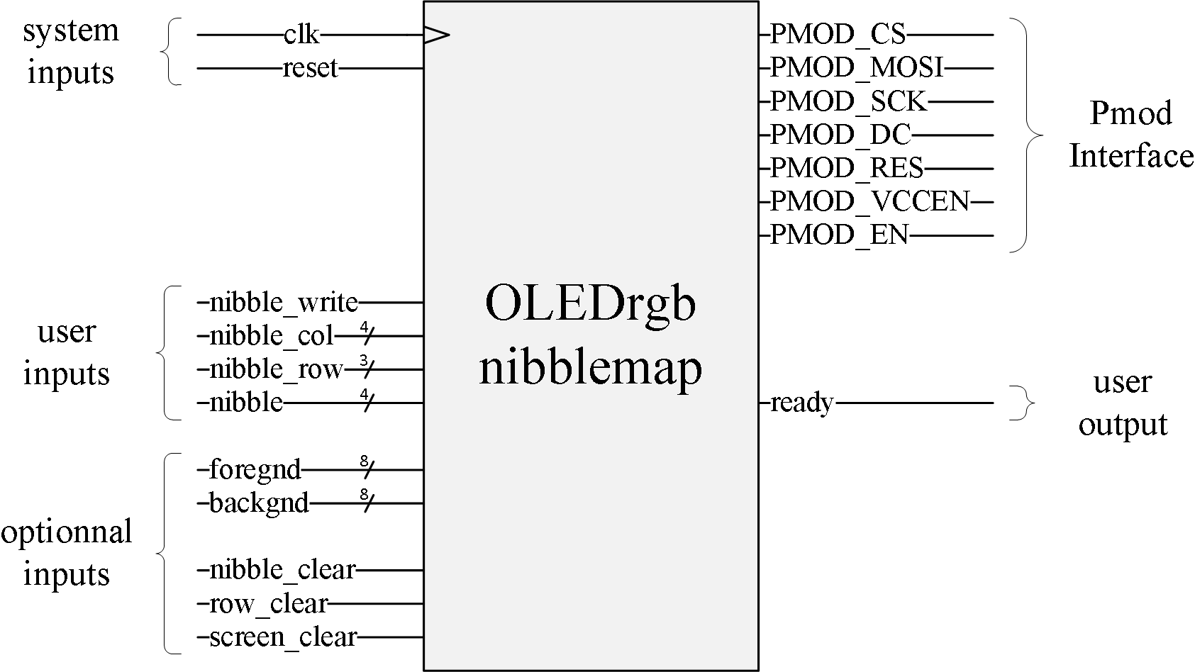
Nibblemap
 ( figure source )
The nibble_row and nibble_col inputs are used to address any position of the 16×8 char array. Position 0,0 is the top left char.
To affect a new char at a given position, user should assert nibble_write, address the concerned char and provide the new hexadecimal value on nibble on the same rising edge of clk. After reading nibble_write at '1', the module will reset the ready output until the operation is performed (see generic timing diagram above). Once ready is set again, the module can accept a new char value and position for display.
The command bit should only be set during one clock cycle, but the parameters should keep their value unchanged until the ready bit is set again. It is possible to change this behavior setting the PARAM_BUFF generic to True. See generic timing diagram above.
User can optionnaly provide a foreground and/or a background color for each char. Default is white on black. Color format is rrrgggbb, the following table give some example colors :
| Hex code | RGB code | Color |
|---|---|---|
| 0x00 | 000-000-00 | Black (default background) |
| 0xFF | 111-111-11 | White (default foreground) |
| 0xE0 | 111-000-00 | Red (izdead) |
| 0x1C | 000-111-00 | Green |
| 0x03 | 000-000-11 | Blue |
Optionnal commands nibble_clear, row_clear and screen_clear respectively fill the addressed char, the addressed line or the whole screen with the background color. These three commands require the module to be ready. During the processing time, the ready output will be reset. If several commands are input at the same time, the priority list is (from high to low) : screen_clear, row_clear, nibble_clear and nibble_write.
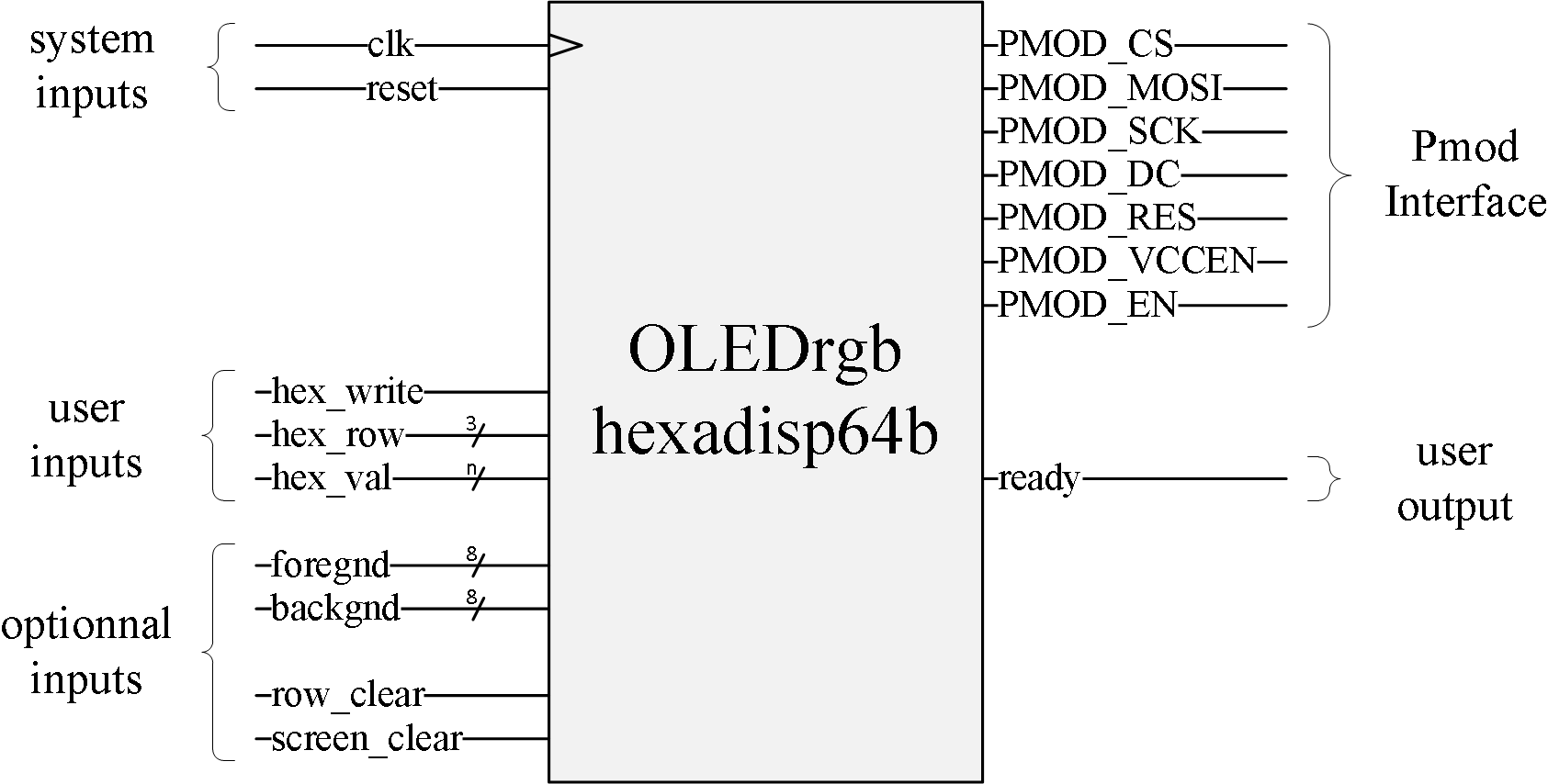
Hexval
 ( figure source )
This module basically works as a frontend for the nibblemap module and provide automatic cursor management. Therefore, it uses this module to work properly and inherits lots of its behavior.
Decimal Display
this work is still in progress… please, come back in a few months, or few years…
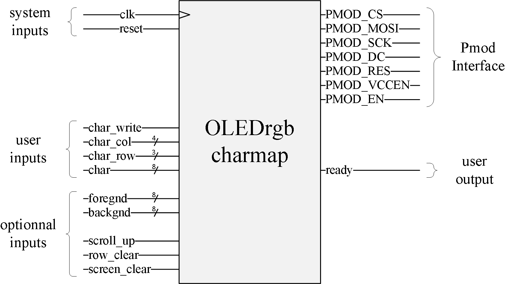
Charmap
 ( figure source )
The char_row and char_col inputs are used to address any position of the 16×8 char array. Position 0,0 is the top left char.
To affect a new char at a given position, user should assert char_write, address the concerned char and provide the new char value on char on the same rising edge of clk. After reading char_write at '1', the module will reset the ready output until the operation is performed (see generic timing diagram above). Once ready is set again, the module can accept a new char value and position for display.
The command bit should only be set during one clock cycle, but the parameters should keep their value unchanged until the ready bit is set again. It is possible to change this behavior setting the PARAM_BUFF generic to True. See generic timing diagram above.
User can optionnaly provide a foreground and/or a background color for each char. Default is white on black. Color format is rrrgggbb, the following table give some example colors :
| Hex code | RGB code | Color |
|---|---|---|
| 0x00 | 000-000-00 | Black (default background) |
| 0xFF | 111-111-11 | White (default foreground) |
| 0xE0 | 111-000-00 | Red (izdead) |
| 0x1C | 000-111-00 | Green |
| 0x03 | 000-000-11 | Blue |
Optionnal commands scroll_up, row_clear and screen_clear respectively scroll text one line up, fill the addressed line or the whole screen with the background color. These three commands require the module to be ready. During the processing time, the ready output will be reset. If several commands are input at the same time, the priority list is (from high to low) : screen_clear, row_clear, scroll_up and char_write.
Terminal
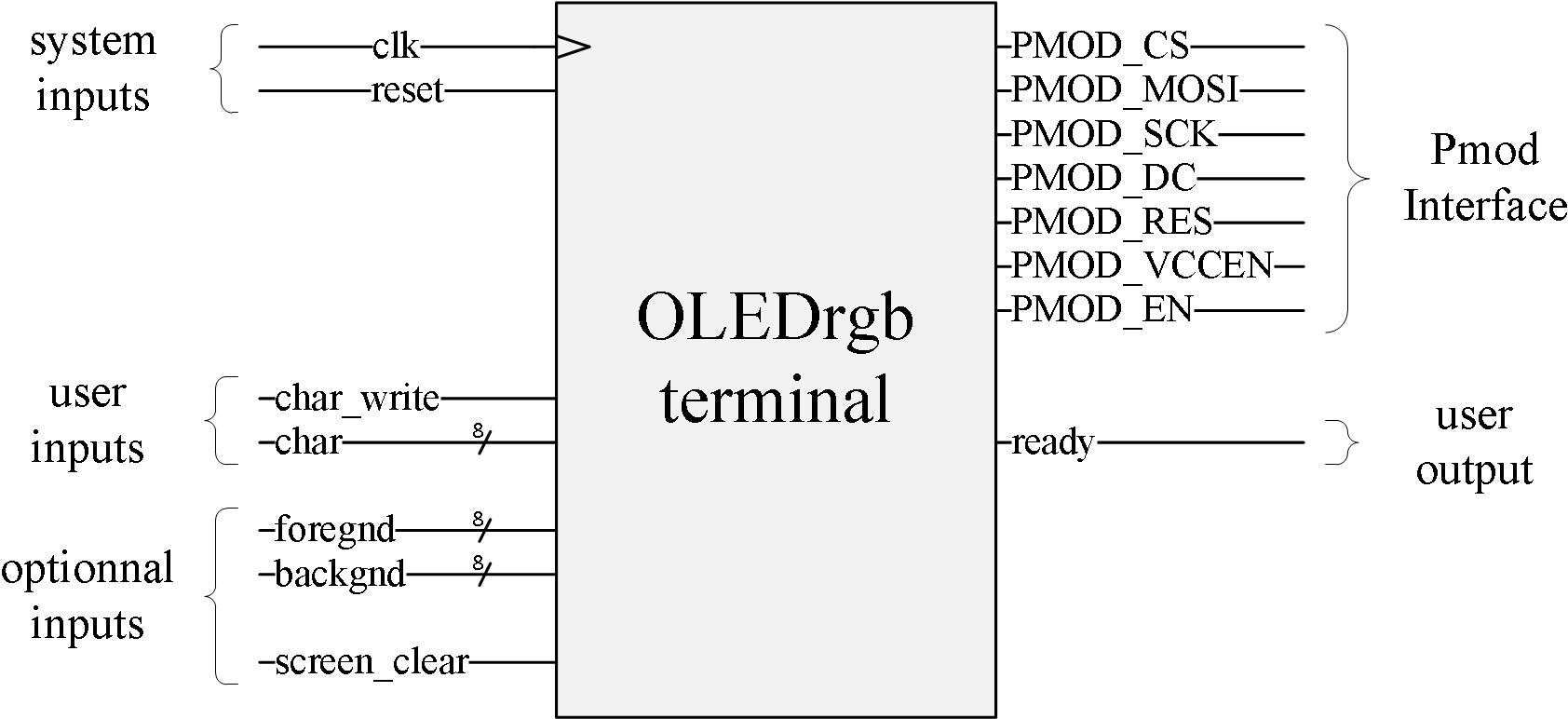 ( figure source )
This module basically works as a frontend for the charmap module and provide automatic cursor management. Therefore, it uses this module to work properly and inherits lots of its behavior.
Sigplot
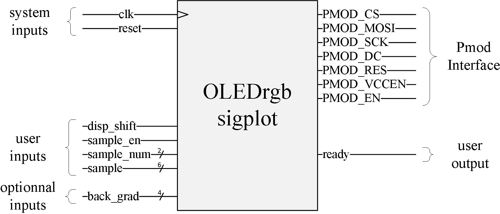 ( figure source )
Using this module, it is possible to display up to 4 plots on the OLED screen. Each time a new sample is input, the sample value shall be presented on sample, the considered curve shall be indicated on sample_num and the sample_en bit should be set on the same rising edge of clk. The plot coordinates follow the mathematical logic instead of the screen address logic, so higher values are displayed at the top of the screen, and lower values at the bottom. It is possible to change this behavior setting the MAX_ON_TOP generic to False.
To provide more flexibility, horizontal shifts are performed as separate commands. It is then possible to input several points per pixel column, or to dynamically change the display scale of new samples. To perform a shift, the disp_shift input must be asserted when the module is ready. It is possible to assert both sample_en and disp_shift at the same time when the module is ready. In this case, the new sample is drawn first, then the display is shifted.
When a new sample point is entered for a given curve and the previous point is still visible on the screen for the same curve, a line is drawn between the two points, regardless the horizontal position of the last point. It is then possible to draw curves at different sampling rates on the same graphic.
When performing a horizontal shift, user can optionnally provide a 4-bit background greyscale value on back_grad. This feature is usefull to indicate triggers, events or timing scales. It is not possible to change the background color of a pixel column once the horizontal shift has been performed.
Curve colors are the following :
| curve ID | Color |
|---|---|
| 00 | Cyan |
| 01 | Green |
| 10 | Purple |
| 11 | Yellow |